
GEAR COUPLING
Equipment couplings are torsionally rigid and are equipped to two types â completely versatile and adaptable/rigid. A entirely flexible coupling contains two hubs with an external gear and two outer sleeves with an interior gear. It truly is a universal coupling for all kinds of applications and accommodates all achievable misalignments (angular, offset and merged) as effectively as large axial times. Devices, bearings, seals, and shafts are for that reason not subjected to the extra forces, sometimes of considerable magnitude, which come up from unavoidable misalignment typically linked with rigid shaft couplings.
A flexible/rigid coupling comprises 1 adaptable geared 50 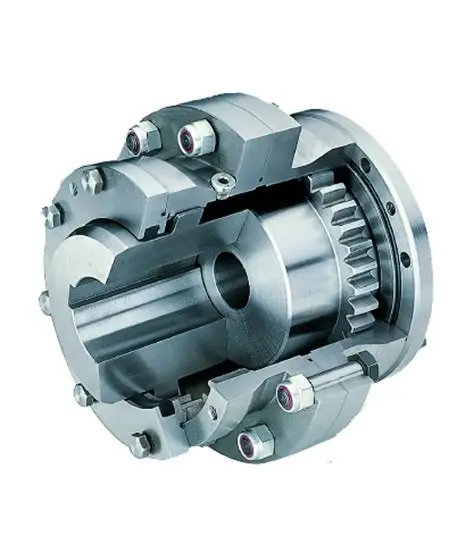 percent and one rigid half. It does not accommodate parallel displacement of shafts but does accommodate angular misalignment. This variety of couplings are primarily utilized for “floating shaft” programs.
Sizes 010 â 070 all have topped teeth with a 20° pressure contact (fig 1). This allows to accommodate up to one,5° static angular misalignment for every gear mesh. Nonetheless, reducing the operational misalignment will improve the life of the coupling as well as the daily life of other machinery parts this sort of as bearings and so on.
Gear COUPLING
gear coupling is a torsionally rigid grease filled coupling consisting of two hubs with external multicrown – and two flanged sleeves with straight inside enamel. The flanged sleeves are bolted jointly with higher energy corrosion safeguarded equipped bolts and nuts. The sleeve is at the opposite side of the flange executed with an endcap (interior for little and screwed for huge measurement couplings) in which the o-ring is situated for sealing needs. The equipment coupling has been developed to transmit the torque amongst these two flanges through friction staying away from fretting corrosion between these faces.
The tooth of hub and sleeve are continually in make contact with with every single other and have been designed with the necessary backlash to accommodate angular-, parallel- and axial misalignment in their misalignment capability. The angular and parallel misalignment ability is decided by the gear tooth layout and is for the common gear max. one.5° degrees (2 x .75°) in total. The axial misalignment potential is limited by the equipment tooth length in the sleeve and can be diverse (optionally).
Click for more articles concerning CHINA GEAR COUPLING.