
Within an epicyclic or planetary gear train, several spur gears distributed evenly around the circumference run between a gear with internal teeth and a gear with exterior teeth on a concentric orbit. The circulation of the spur equipment takes place in analogy to the orbiting of the planets in the solar system. This is how planetary gears obtained their name.
The elements of a planetary gear train could be split into four main constituents.
The housing with integrated internal teeth is actually a ring gear. In the majority of cases the housing is fixed. The traveling sun pinion is in the heart of the ring gear, and is coaxially organized with regards to the output. Sunlight pinion is usually mounted on a clamping system in order to give the mechanical connection to the electric motor shaft. During procedure, the planetary gears, which will be attached on a planetary carrier, roll between your sunlight pinion and the band gear. The planetary carrier as well represents the outcome shaft of the gearbox.
The sole reason for the planetary gears is to transfer the required torque. The quantity of teeth has no effect on the tranny ratio of the gearbox. The quantity of planets can also vary. As the quantity of planetary gears boosts, the distribution of the strain increases and therefore the torque which can be transmitted. Raising the amount of tooth engagements as well reduces the rolling vitality. Since only section of the total outcome has to be transmitted as rolling electric power, a planetary gear is extremely efficient. The benefit of a planetary equipment compared to a single spur gear lies in this load distribution. It is therefore possible to transmit excessive torques wit
h high efficiency with a concise design using planetary gears.
Provided that the ring gear includes a constant size, different ratios could be realized by different the number of teeth of sunlight gear and the number of teeth of the planetary gears. Small the sun gear, the higher the ratio. Technically, a meaningful ratio selection for a planetary level is approx. 3:1 to 10:1, since the planetary gears and sunlight gear are extremely little above and below these ratios. Bigger ratios can be obtained by connecting several planetary levels in series in the same ring gear. In cases like this, we talk about multi-stage gearboxes.
With planetary gearboxes the speeds and torques can be overlaid by having a band gear that’s not fixed but is driven in virtually any direction of rotation. Additionally it is possible to fix the drive shaft so as to grab the torque via the ring equipment. Planetary gearboxes have grown to be extremely important in many regions of mechanical engineering.
They have become particularly well established in areas where high output levels and fast speeds should be transmitted with favorable mass inertia ratio adaptation. High transmission ratios may also easily be performed with planetary gearboxes. Because of their positive properties and small design, the gearboxes have various potential uses in industrial applications.
The advantages of planetary gearboxes:
Coaxial arrangement of input shaft and output shaft
Load distribution to many planetary gears
High efficiency due to low rolling power
Nearly unlimited transmission ratio options due to mixture of several planet stages
Ideal as planetary switching gear because of fixing this or that part of the gearbox
Chance for use as overriding gearbox
Favorable volume output
Suitability for a wide variety of applications
Epicyclic gearbox can be an automatic type gearbox where parallel shafts and gears set up from manual gear package are replaced with more compact and more reliable sun and planetary type of gears arrangement as well as the manual clutch from manual ability train is changed with hydro coupled clutch or torque convertor which in turn made the transmission automatic.
The idea of epicyclic gear box is taken from the solar system which is considered to an ideal arrangement of objects.
The epicyclic gearbox usually includes the P N R D S (Parking, Neutral, Reverse, Drive, Sport) settings which is obtained by fixing of sun and planetary gears in line with the need of the travel.
Components of Epicyclic Gearbox
1. Ring gear- It is a type of gear which looks like a ring and also have angular trim teethes at its interior surface ,and is put in outermost placement in en epicyclic gearbox, the inner teethes of ring equipment is in constant mesh at outer point with the group of planetary gears ,it is also known as annular ring.
2. Sun gear- It is the equipment with angular trim teethes and is positioned in the center of the epicyclic gearbox; sunlight gear is in continuous mesh at inner level with the planetary gears and is usually connected with the type shaft of the epicyclic gear box.
One or more sunlight gears can be used for attaining different output.
3. Planet gears- These are small gears found in between ring and sun equipment , the teethes of the planet gears are in regular mesh with sunlight and the ring equipment at both inner and outer factors respectively.
The axis of the planet gears are mounted on the earth carrier which is carrying the output shaft of the epicyclic gearbox.
The earth gears can rotate about their axis and also can revolve between the ring and sunlight gear exactly like our solar system.
4. Planet carrier- It is a carrier fastened with the axis of the earth gears and is responsible for final transmitting of the end result to the result shaft.
The planet gears rotate over the carrier and the revolution of the planetary gears causes rotation of the carrier.
5. Brake or clutch band- The device used to fix the annular gear, sun gear and planetary gear and is managed by the brake or clutch of the automobile.
Working of Epicyclic Gearbox
The working principle of the epicyclic gearbox is based on 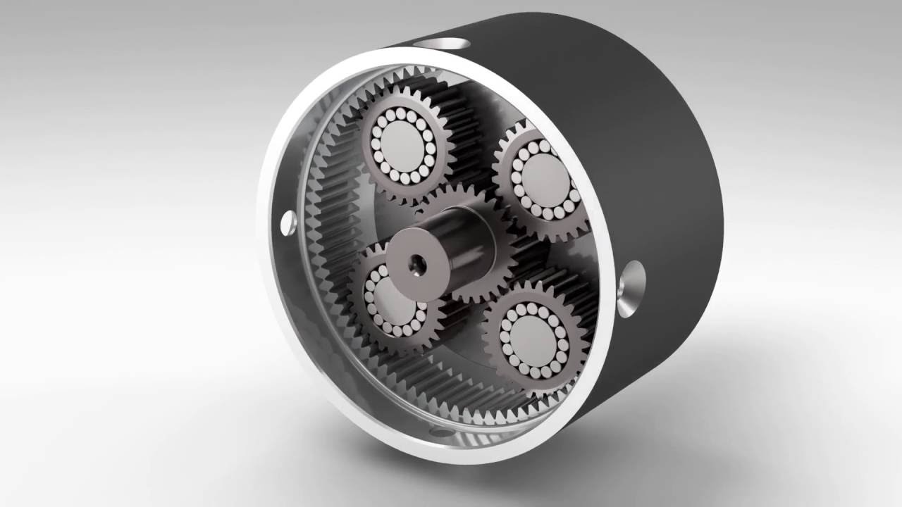 the fact the fixing the gears i.e. sun gear, planetary gears and annular gear is done to get the needed torque or quickness output. As fixing the above triggers the variation in gear ratios from great torque to high rate. So let’s see how these ratios are obtained
First gear ratio
This provide high torque ratios to the automobile which helps the automobile to move from its initial state and is obtained by fixing the annular gear which in turn causes the planet carrier to rotate with the power supplied to sunlight gear.
Second gear ratio
This gives high speed ratios to the vehicle which helps the automobile to attain higher speed throughout a drive, these ratios are obtained by fixing the sun gear which makes the planet carrier the powered member and annular the traveling member as a way to achieve high speed ratios.
Reverse gear ratio
This gear reverses the direction of the output shaft which reverses the direction of the vehicle, this gear is attained by fixing the earth gear carrier which in turn makes the annular gear the influenced member and the sun gear the driver member.
Note- More acceleration or torque ratios may be accomplished by increasing the quantity planet and sun equipment in epicyclic gear box.
High-speed epicyclic gears could be built relatively small as the energy is distributed over several meshes. This effects in a low capacity to weight ratio and, together with lower pitch line velocity, brings about improved efficiency. The tiny equipment diameters produce lower occasions of inertia, significantly lowering acceleration and deceleration torque when starting and braking.
The coaxial design permits smaller and therefore more cost-effective foundations, enabling building costs to be kept low or entire generator sets to be integrated in containers.
The reasons why epicyclic gearing is used have already been covered in this magazine, so we’ll expand on the topic in only a few places. Let’s commence by examining a significant facet of any project: cost. Epicyclic gearing is normally less expensive, when tooled properly. Being an wouldn’t normally consider making a 100-piece large amount of gears on an N/C milling equipment with an application cutter or ball end mill, you need to certainly not consider making a 100-piece lot of epicyclic carriers on an N/C mill. To preserve carriers within realistic manufacturing costs they must be made from castings and tooled on single-purpose equipment with multiple cutters simultaneously removing material.
Size is another aspect. Epicyclic gear models are used because they are smaller than offset equipment sets since the load can be shared among the planed gears. This makes them lighter and more compact, versus countershaft gearboxes. As well, when configured effectively, epicyclic gear models are more efficient. The next example illustrates these rewards. Let’s presume that we’re building a high-speed gearbox to satisfy the following requirements:
• A turbine provides 6,000 horsepower at 16,000 RPM to the suggestions shaft.
• The end result from the gearbox must travel a generator at 900 RPM.
• The design existence is to be 10,000 hours.
With these requirements in mind, let’s look at three conceivable solutions, one involving an individual branch, two-stage helical gear set. A second solution takes the original gear placed and splits the two-stage reduction into two branches, and the 3rd calls for utilizing a two-stage planetary or superstar epicyclic. In this instance, we chose the star. Let’s examine each one of these in greater detail, looking at their ratios and resulting weights.
The first solution-a single branch, two-stage helical gear set-has two identical ratios, produced from taking the square base of the final ratio (7.70). Along the way of reviewing this remedy we recognize its size and pounds is very large. To lessen the weight we then explore the possibility of making two branches of an identical arrangement, as seen in the second alternatives. This cuts tooth loading and decreases both size and weight considerably . We finally reach our third choice, which is the two-stage superstar epicyclic. With three planets this equipment train reduces tooth loading considerably from the primary approach, and a somewhat smaller amount from alternative two (find “methodology” at end, and Figure 6).
The unique design characteristics of epicyclic gears are a huge part of what makes them so useful, yet these very characteristics could make designing them a challenge. Within the next sections we’ll explore relative speeds, torque splits, and meshing factors. Our goal is to create it easy for you to understand and use epicyclic gearing’s unique design characteristics.
Relative Speeds
Let’s begin by looking for how relative speeds work together with different arrangements. In the star arrangement the carrier is set, and the relative speeds of sunlight, planet, and ring are simply dependant on the speed of one member and the amount of teeth in each equipment.
In a planetary arrangement the band gear is fixed, and planets orbit the sun while rotating on the planet shaft. In this arrangement the relative speeds of sunlight and planets are dependant on the amount of teeth in each gear and the velocity of the carrier.
Things get a little trickier when working with coupled epicyclic gears, since relative speeds might not be intuitive. Hence, it is imperative to at all times calculate the speed of sunlight, planet, and ring in accordance with the carrier. Understand that even in a solar arrangement where the sunlight is fixed it has a speed marriage with the planet-it isn’t zero RPM at the mesh.
Torque Splits
When contemplating torque splits one assumes the torque to be divided among the planets similarly, but this may not be a valid assumption. Member support and the amount of planets determine the torque split represented by an “effective” number of planets. This number in epicyclic sets designed with two or three planets is in most cases equal to you see, the amount of planets. When a lot more than three planets are utilized, however, the effective quantity of planets is generally less than you see, the number of planets.
Let’s look for torque splits with regards to set support and floating support of the members. With set support, all members are backed in bearings. The centers of the sun, band, and carrier will not be coincident because of manufacturing tolerances. Due to this fewer planets will be simultaneously in mesh, producing a lower effective quantity of planets posting the load. With floating support, one or two associates are allowed a little amount of radial liberty or float, which allows the sun, ring, and carrier to get a posture where their centers will be coincident. This float could possibly be less than .001-.002 inches. With floating support three planets will be in mesh, resulting in a higher effective quantity of planets sharing the load.
Multiple Mesh Considerations
At this time let’s explore the multiple mesh considerations that should be made when designing epicyclic gears. Initial we should translate RPM into mesh velocities and determine the number of load software cycles per device of time for every member. The first rung on the ladder in this determination is usually to calculate the speeds of every of the members relative to the carrier. For instance, if the sun equipment is rotating at +1700 RPM and the carrier can be rotating at +400 RPM the velocity of sunlight gear relative to the carrier is +1300 RPM, and the speeds of planet and ring gears could be calculated by that swiftness and the numbers of teeth in each of the gears. The use of signs to stand for clockwise and counter-clockwise rotation is normally important here. If the sun is rotating at +1700 RPM (clockwise) and the carrier is rotating -400 RPM (counter-clockwise), the relative swiftness between the two members can be +1700-(-400), or +2100 RPM.
The second step is to decide the quantity of load application cycles. Since the sun and ring gears mesh with multiple planets, the number of load cycles per revolution in accordance with the carrier will end up being equal to the number of planets. The planets, on the other hand, will experience only 1 bi-directional load application per relative revolution. It meshes with sunlight and ring, but the load can be on opposing sides of one’s teeth, leading to one fully reversed stress cycle. Thus the earth is considered an idler, and the allowable pressure must be reduced 30 percent from the worthiness for a unidirectional load request.
As noted above, the torque on the epicyclic people is divided among the planets. In analyzing the stress and your life of the participants we must consider the resultant loading at each mesh. We locate the idea of torque per mesh to become somewhat confusing in epicyclic gear analysis and prefer to check out the tangential load at each mesh. For example, in searching at the tangential load at the sun-world mesh, we have the torque on sunlight gear and divide it by the successful number of planets and the functioning pitch radius. This tangential load, combined with peripheral speed, can be used to compute the energy transmitted at each mesh and, altered by the strain cycles per revolution, the life span expectancy of each component.
Furthermore to these issues there can also be assembly complications that require addressing. For example, putting one planet ready between sun and ring fixes the angular location of sunlight to the ring. The next planet(s) is now able to be assembled just in discreet locations where in fact the sun and ring could be at the same time involved. The “least mesh angle” from the primary planet that will support simultaneous mesh of the next planet is add up to 360° divided by the sum of the numbers of teeth in the sun and the ring. Therefore, so as to assemble added planets, they must always be spaced at multiples of this least mesh angle. If one desires to have the same spacing of the planets in a straightforward epicyclic set, planets may be spaced equally when the sum of the amount of teeth in the sun and band is definitely divisible by the number of planets to an integer. The same guidelines apply in a compound epicyclic, but the fixed coupling of the planets offers another level of complexity, and right planet spacing may necessitate match marking of pearly whites.
With multiple parts in mesh, losses should be considered at each mesh as a way to measure the efficiency of the unit. Power transmitted at each mesh, not input power, can be used to compute power reduction. For simple epicyclic models, the total electricity transmitted through the sun-planet mesh and ring-world mesh may be significantly less than input electrical power. This is among the reasons that easy planetary epicyclic sets are more efficient than other reducer plans. In contrast, for many coupled epicyclic pieces total electricity transmitted internally through each mesh may be higher than input power.
What of electric power at the mesh? For simple and compound epicyclic models, calculate pitch line velocities and tangential loads to compute ability at each mesh. Ideals can be obtained from the earth torque relative speed, and the functioning pitch diameters with sun and ring. Coupled epicyclic models present more complex issues. Components of two epicyclic units can be coupled 36 various ways using one source, one output, and one response. Some arrangements split the power, although some recirculate vitality internally. For these kind of epicyclic units, tangential loads at each mesh can only be determined through the use of free-body diagrams. Also, the factors of two epicyclic models can be coupled nine different ways in a series, using one insight, one end result, and two reactions. Let’s look at a few examples.
In the “split-vitality” coupled set shown in Figure 7, 85 percent of the transmitted ability flows to band gear #1 and 15 percent to band gear #2. The result is that this coupled gear set can be smaller sized than series coupled models because the vitality is split between your two components. When coupling epicyclic sets in a series, 0 percent of the energy will be transmitted through each arranged.
Our next case in point depicts a established with “power recirculation.” This gear set happens when torque gets locked in the machine in a manner similar to what occurs in a “four-square” test process of vehicle drive axles. With the torque locked in the machine, the horsepower at each mesh within the loop enhances as speed increases. Consequently, this set will encounter much higher power losses at each mesh, resulting in significantly lower unit efficiency .
Number 9 depicts a free-body diagram of an epicyclic arrangement that activities electric power recirculation. A cursory research of this free-human body diagram clarifies the 60 percent proficiency of the recirculating arranged demonstrated in Figure 8. Because the planets will be rigidly coupled at the same time, the summation of forces on the two gears must equal zero. The drive at sunlight gear mesh outcomes from the torque suggestions to sunlight gear. The force at the next ring gear mesh outcomes from the result torque on the ring gear. The ratio being 41.1:1, end result torque is 41.1 times input torque. Adjusting for a pitch radius difference of, say, 3:1, the pressure on the second planet will be about 14 times the pressure on the first planet at sunlight gear mesh. Consequently, for the summation of forces to equate to zero, the tangential load at the first ring gear should be approximately 13 occasions the tangential load at sunlight gear. If we believe the pitch range velocities to become the same at sunlight mesh and ring mesh, the power loss at the band mesh will be about 13 times higher than the power loss at the sun mesh .
epicyclic gearbox
Tags: